
Jörg Sigle's
Emulator Ultra rotary wheel fix
To start with a legal statement: Registered trademarks are the properties of their owners; I do not imply that E-mu Ultras typically should need the fix described herein; the provided information is intended only for scientific or amateur use; please keep in mind that trying to service your E-mu on your own may void your warranty; please keep in mind that at least the system power supply and the backlight power supply on the motherboard may produce dangerous voltages. I do not accept any liabilities for the results of your own action, even if you might claim that I should have provided some inspiration. If you continue to read, this is on your own risk, and if you think that the contents of this page might violate any law in your country or any right or anything else that they should not violate, please be informed that I do not allow you to read any further. If you should know that there might be a legal problem with this page at all, please do not hesitate to send me a free (!) e-mail with further information in order to enable me to comply with any necessary regulations. And finally, if somebody should open up a business doing this procedure on many Ultras or if some hardware designers should not have known this solution or its relevance to specific existing or future designs (at E-mu or elsewhere), and thus this page should be a contribution to someone make a huge profit - please feel free to share a bit of it and support my projects described elsewhere on this web site. :-)
I do provide this page because after mentioning my solution in the Emulator list, I received about 4 responses within the first two days asking for details, one communicating that the problem might have been known for years. So I guess that a description of my experience might be useful for others as well.
When turning the rotary wheel encoder of my Emulator Ultra swiftly, it made the controlled parameter hop backwards relatively often, so that going up or down fast could become a bit frustrating. Using the same wheel slowly worked perfectly.
I could have given the device into warranty service, but I did not want to because I would have had to prepare it for shipment, give it away for an unknown duration of time, and was not sure whether warranty service would reliably fix the problem. Or hop into the car and drive to Cologne with it - several hundred kilometers and several hours with German Autobahn traffic with so many people who do not apply the basic knowledge that safety distance is more vital than large diameter potency replacement exhausts [...].
I guessed that the problem might be caused by the wheel encoder producing some noise within its encoding signal. The hypothesis was that, in a simplified description, turning the encoder swiftly would make some rotating encoding contacts move too fast over some printed circuit board with an encoding contact pattern that might not have a perfect surface, thereby losing contact even while over supposedly conducting parts of the encoding pattern. A similar phenomenon is known from almost any kind of mechanical switch or key: usually you won't get clean transitions from on to off and the other way round from any of these, but you will get the intended signal together with some noise - a random number of quick changes between the two states before the final condition remains stable. Usually, the noise occurs so fast, that you won't notice it after switching on a light bulb, but a fast microcomputer controlled by such a switch may certainly see any single transition, including the noisy spikes - and e.g., recognize and process 5 keystrokes instead of one. Or get mixed up regarding the direction in which the rotary wheel has been spun.
Such noise can be eliminated by using an element that you may know from the cord patches area in the Emulator synthesis engine, or from the very interesting Emulator Modular manual which I glanced at a few days ago, as a lag processor. However, putting one little hardware lag processor to each key of a complex microcomputer keyboard needs hardware, logistics and soldering time. Thus, in most modern microcomputers, software algorithms expect the noise and ignore very brief, repeating signals. I guess, however, that the software in my Emulator did not expect the rotary wheel encoder to produce as broad noise peaks as it actually does. (By the way - I'm somewhat surprised either: I would rather have expected an optical encoder, as in a mouse, or maybe one using magnets and REED contacts - well, the latter might need to much mechanics for an acceptable solution.)
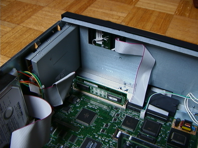
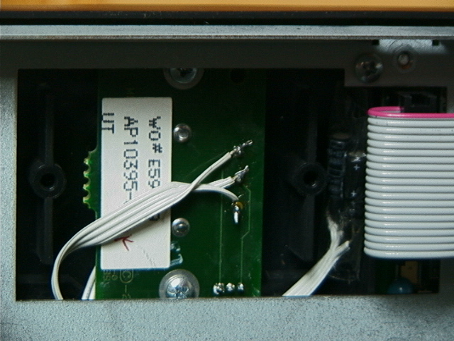
To test the hypothesis, I first located the wheel encoder, and used a scope to look at the signals on its three connecting pins. For this purpose, I attached a separate ground wire from the scope to one of the empty ROM slot metal clamps in the sampler, and measured the voltage on the three connecting wires of the rotary wheel encoder. Having found out that the middle one is ground, I used an IC socket, attached the measurement leads to its pins, and held it over the pins protruding from the wheel encoder printed circuit board, to make usable and stable contact for both measurement leads without too much construction time again. Turning the encoder gave an oscillogramme that supported my hypothesis.
(The following is not recommended, because I feel the toy is too expensive and the reward too little: If a scope is not available, theoretically, it should be possible to use the sampling input of the E-mu itself to sample and view the signals, a thought that has some philosophically interesting appeal, but if I should have to do that for some reason, I would not without some preceeding measurements establish a direct connection between these two parts of the Emu, not even between the two respective ground lines. An A.C. connection via suitably chosen capacitors could probably be used with limited risk. Also, the sound input of some PC sound card could be used - but use similar caution, don't establish any D.C. link just so. Yes, an A.C. link is sufficient to look at spikes.)
Because the two leads which carried signals when the encoder was turned both carried a 5 V signal when the encoder rested, I guessed that
In this case, "noise" would occur in the form of quick spikes back to 5 V, delivered through the pull up resistors. And such noise could easily be eliminated by adding two capacitors: one between each signal line and ground. Current refilling the capacitors via these pull up resistors would take some time to re-establish 5 V on the signal lines, both (unimportant) at the intended end of the low signal and (very welcome) when the encoder would erroneously lose contact for a short duration, whereas the (maybe important) falling edge of the encoder finding contact at the important beginning of the intended signal and the (maybe important) maintained low level during the signal would not be affected at all. No additional elements needed.
Thus, I tried out a 0.1 µF capacitor between two of the lines. The spikes were cut back by a substantial amount. Then, i tried 4.7 µF. The spikes were gone, but the time it took too refill the capacitor via the pull up resistor towards 5 V easily approached the duration of a normal pulse with while turning the wheel at moderate speed. So I decided to use the 0.1 µF types (they were also physically smaller) and soldered them directly to the soldering pins of the encoder.
Testing the result (and generating an oscillogramme, finally without being required to hold an IC socket with a plugged in capacitor to a small PCB using one hand, support the measurement leads with the second, and turn a wheel encoder swiftly with the third), I was not completely pleased because at least a few spikes seemed to remain big enough to be recognized (mistakenly) as coding events by the software. So I added 1 µF capacitors in parallel to the 0.1 µF ones, the new ones soldered to the pins of the cable connector. This produced satisfactory results, and so, to save space and parts, I removed the 0.1 µF ones again. Then, I was happy with the test results and tried to put everything together again.
However, I had to notice that my 1 µF capacitors (63 V with conventional pins, did not have any other ones...) were too big to fit under the metal backplane cover of the Emulator front. So I removed them again, and did what you finally might chose to try out as well:
Images and a diagram:
Here are some supporting measures:
The required parts should be available in any little store or catalog that offers electronic parts. Exact values are uncritical as long as the dimensions match. They are cheap - should not cost more than a few Cents. The described procedure is relatively simple and you should be able to perform it in a few minutes, certainly not more than an hour. Of course, I wish those who try it out good luck.
If you try it, it would be very kind if you would provide some feedback in the Emulator mailing list. Having heard of a few others with the same problem supports my decision not to have given the machine into the warranty service repair - I guess, the capacitors are the right things to add to the specific combination of encoder and software that has been used for the Ultra.
I remember vaguely having heard of similar problems with the other keys on the front panel. If such problems should actually occur, it would of course be possible to add capacitors there as well, but that would require some studying regarding the available wires, their voltages, maybe optional diodes or maybe additional integrated circuits. My E-mu doesn't have any problems with this respect yet.
I think that another alternative would be to ask E-mu to address the issue in the process of their software update. When I programmed routines to monitor hardware switches (some time ago), they included constants defining the minimum duration of polarity changes to be interpreted a result of switch operation and not noise. It should be relatively easy to increase such a value in the Emulator OS, but there should be at least some preceeding research, because, as I said above, the noise that I observed contained high numbers of spikes with surprisingly long durations .
Maybe I will provide a photo and drawings of the oscillogrammes later, but I guess this text should describe the procedure with sufficient clarity anyway. A German (slightly shorter) version that I already sent away by e-mail is available upon request.
[...Final remark deleted. Don't want to appear overly wise :-) ...]
Here is a nice remark: has anyone noticed the text more sugar! printed somewhere on the Emulator Ultra motherboard? I have, and I think just like this I do like some other little design features in this device. It may not be perfect, but I feel that the people who made it must have enjoyed making it to some degree. If not, E-mu •must• have an Ultra ... sophisticated marketing unit... :-)
To make this page complete: another passage from my original posting.
"Btw, here is a suggestion for future Emus: The wheels on the Morpheus and especially on the Digitech Studio Vocalist feel better than that of the Ultra: Morpheus' wheel is smaller, but has good grip, and Vocalist's is larger but also with good grip and can be spinned with a bit of impetus - E-mu Ultra's encoder in contrast, is too large to grip it like the Morpheus', but it is also too smooth on its outer rim, too light plastic, and the knob tilts too easily against the encoder axis too be able to spin it as neatly as the Vocalist's."
Inspired by this page, Ray designed professionally made replacements for the little rotary encoder boards in 2019, where capacitors are already included. These look absolutely neat :-)
Ray kindly sent me some samples for testing. I put one into the E-Mu 6400 Ultra pictured above, and it appears to work well.
There are two board sizes - a smaller and a larger one:
Ray says he originally made replacement boards for earlier models predating the E4 series, so he knows which Emulator type requires which board size.
Exchanging the encoder board requires de-soldering the 3 pin cable connector from the old board and soldering it to the new board. It's neither very difficult nor all too critical - but you might want to use a soldering iron with a broad tip or a hot air soldering station that can heat all three pins at the same time.
Maybe the front panel should be removed and its rear portion detached, however, in either case: The cable between the rotary encoder and keypad boards is relatively short. So removing the front panel from the machine, and then detaching its metal back with the display, provides a bit of extra space for the soldering exercise. It's only a few more screws, plus a few cables. - Please don't overlook the additional screw at the headphone plug, and do remember which of the two headphone related cables goes to the upper or lower portion of that terminal - and do read the other hints further above :-)
You may find Ray in these forums (Mind you: Links to Facebook carry data protection and other dire implications, but anyway):
Ray also made several E-mu tools - please see below.
 This Web page was prepared by myself,
and so were all included graphic elements.
© 18.06.2002, 09.12.2002, 14.11.2005, 23.03.2009, 24.07.2020 Dr. med. Jörg M. Sigle, Kunstvolle EDV & Elektronik